![[Jump to Cover]](cover.gif) |
![[Jump to Contents]](contents.gif) |
![[Jump to Introduction]](introduc.gif) |
![[Jump to Concepts]](concepts.gif) |
![[Jump to Realization]](realiza.gif) |
![[Jump to Conclusion]](conclusi.gif) |
![[Jump to Appendix]](appendix.gif) |
3.3 Options for System Integration
The previous analysis of the different systems at the CCE show that they provide a high potential to be integrated into a multi-technological learning system. The interfaces that the systems offer to the ‘outside world’ are quite different, but there are ways to equalize these differences.For the mechanical systems (Lego Technic, Märklin Metall, and Festo pneumatics), adapters could be designed that consist of original parts from two systems an thus provide a compatible interface to each of them. E.g., adapters made of angle sections from Märklin Metall, attached to standard Lego bricks will enable kids to design a very stable metal construction as a base for a large functional Lego model.
At a first glance, the Festo pneumatic system seems more suitable to be combined with Märklin Metall than with Lego. This is due to the comparably high force that pneumatic cylinders produce when in action. However, since flow control valves can be employed to reduce the cylinders’ speed, Festo-powered Lego models will also be possible. Suitable hardware adapters can be realized using Lego Technic parts.
Compared to the mechanical interfaces, the adaptation of the electrical parts is much more challenging. Since the Crickets only provide 9V, 150mA outputs and a 24V voltage is required for Festo pneumatic valves, an amplifier is needed to combine these systems. For Lego and other high-power motors, currents up to about 5A are desired, which should also be reversible.
In accordance with the requirements set in the beginning (see section 2.3.2), the Crickets may not be altered in order to preserve their universal usability for other purposes. For this reason, add-on modules have been designed that ride on top of the Crickets.
These add-ons will be described in the following
sections, emphasizing on the design principles as well as on hints for
the practical construction. However, there will be no details on the electronic
devices that have been used (i.e., diodes, photocouplers, MOSFETs , etc.),
so please refer to the relevant literature for this.
3.4 Design of Cricket Hardware Add-Ons
The two different Cricket add-ons have been designed to extend the Crickets’ electrical abilities. Although they have been named "Pneumatic Cricket" and "High Power Cricket" respectively, these modules can be used universally. This means that the Pneumatic Cricket’s application is not restricted to controlling pneumatics, and the High Power Cricket can be used for low power applications just as well. The names are merely related to their current use at the CCE.Based on the idea to design the add-ons as compact modules that can ride on the Cricket in order to adapt it to different needs, the area of the circuit boards has been limited to the Cricket’s outline. Certain areas have been cut out to give access to switches and LEDs on the Cricket below. To fix it on the Cricket, an add-on module is simply plugged into the Cricket’s input and output ports.
Neither of the two modules uses the Cricket’s input ports, as those are very flexible and need not be changed for the desired applications. The only reason for being plugged into these ports is to use the pins for higher mechanical stability. Thus, the inputs are merely routed through to the corresponding input connectors on the add-on module.
The only way to provide an application with more power and voltage than the Cricket can deliver is to use an external power supply. This may either be a transformer power supply on the mains or a powerful battery pack providing the desired voltage. Depending on the requirements of the actor devices, appropriate voltages may be connected to the Pneumatic Cricket and High Power Cricket add-ons.
When dealing with motors and other electrical devices of high power, the design always has to cope with harmful noise or voltage peaks that may occur. Their origin can be the sparks produced at the motor’s brushes or the negative voltage that is induced in the motor when the power is cut. On the one hand, the electronic devices on the amplifier module have to be dimensioned to stand this. On the other hand, the sensitive electronics on the Cricket must be protected from harmful voltages.
 |
A save way to achieve conformity with the latter requirement is to use photocouplers to completely separate the Cricket’s electronics from the power circuit. There is no way how harmful interference from the outputs could get into the Crickets’ electronics. |
Such devices have been integrated into both the Pneumatic Cricket and the High Power Cricket modules, even if the small magnetic valves from Festo do not produce such noise or peaks. The reason for this precautionary measure is that the add-on modules may also be used for different applications where without photocouplers, malfunction and even damage of the Crickets might occur.
3.4.1 Pneumatic Cricket
The Cricket’s motor outputs provide three states for each motor, which are referred to as ‘thisway on’, ‘thatway on’, and ‘off’ in Cricket Logo. As the solenoid coils in pneumatic valves can only be switched on or off, the reverse direction is not needed. Taking this into account, it is obvious that more than two pneumatic valves can be controlled by a single Cricket.There are two possibilities how to use this extra information. The first one is to control four valves. However, they could not be controlled independently, because the forth state of the motor output is not provided, as it would mean ‘turn left and right at the same time’. The other possibility is to use only three valves. They could be controlled independently with a simple logic on the add-on module, as shown in the following table:
| Cricket motor output states, | Active pneumatic valves, | ||
| X: | Y: | possibility 1: | possibility 2: |
| 0 | 0 | - | - |
| 0 | r | A | A |
| 0 | l | B | B |
| r | 0 | C | C |
| r | r | C, A | A, B |
| r | l | C, B | B, C |
| l | 0 | D | A, C |
| l | r | D, A | A, B, C |
| l | l | D, B | - |
Thinking of many applications that could possibly use four actor devices which do not require to be controlled independently (e.g., the pinball game described in section 3.1, or a sequential flashlight effect), it has been decided to design and build up Pneumatic Cricket add-on modules according to the first possibility.
- Schematic
In order to realize the desired functionality, a pair of photocouplers is connected to each Cricket output in opposite direction. Due to the Cricket’s output logic, none or just one of the couplers is active, but never both at the same time. The output transistor of each photocoupler pulls up the gate of the MOSFET connected to it when active. Otherwise, each gate is pulled down to 0V by a 10 kOhm resistor.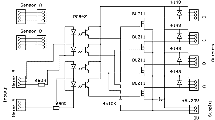
MOSFETs have been chosen for this circuit because of their high efficiency. This is not necessary for the pneumatic application, where only low-power (<2W) electromagnets are to be driven. For this, bipolar transistors could have been used just as well. But since there will probably be applications that demand for more power (e.g., a series of bright lamps), the MOSFET solution has been preferred.
While the transistors limit the circuit’s maximum input voltage to 50V DC (30V has been specified for safety reasons), the maximum current is determined by the 0.1 inch female headers used as output sockets. Their guaranteed rating is 1A, but they have been tested successfully at 5A continuous for 30 minutes without getting too warm. The reason why these connectors are used here is to keep the add-on module compatible to the standard Cricket actor plugs.
The input current of the photocoupler’s LEDs is limited to 12mA per Cricket output by the 680 Ohm resistors. This is enough to drive the phototransistors without draining too much energy from the Cricket’s battery.
- Parts List and Layout
All parts used for the Pneumatic Cricket add-on module have been ordered from the electronics mail-order warehouse Conrad , Germany. The order numbers in the following parts list refer to their catalog. However, these are all standard parts that should be available from most electronics stores.| Amount | Type | Description | Order Number |
| 4 | BUZ 11 = IRFZ34N | N-type MOSFET | 15 94 41 |
| 1 | 22µF 50V | Capacitor 8x6.5mm | 47 29 05 |
| 1 | PC847 | 4 photocouplers | 18 70 20 |
| 2 | 680R, 1/4W, 5% | Resistor | 40 32 37 |
| 1 | 4x10K, 1/8W, 2% | Resistor Network, 5 pins | 41 60 29 |
| 4 | 1 N 4148 | Diode | 16 22 80 |
| 2 | Male 8 pin header | Cut: 2+6+4+4 pins | 73 94 48 |
| 2 | Female 20 pin header | Cut: 12+4+4 pins | 73 63 50 |
| 1 | 2 pin, 3.5mm grid | Supply cable connector | 72 99 81 |
If the cable connector is hard to get because of its 3.5mm grid (5mm is standard), an alternative could be to solder the pair of wires right into the board and use any kind of plug-and-socket connection on the cable.
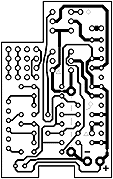
The layout for this board has been created in single-layer mode. Due to the limited space, a few wire bridges could not be avoided. Except for the simple bridge under the IC package, the pads concerned have been marked on the layout: There are two larger pads that may be connected using a piece of solid copper wire. On the layout, these two pads have been marked with a dashed line in between. The two remaining wire connections have identifier symbols next to them – rectangles and triangles, respectively. These connections should be inserted on the bottom side in the very end of assembly, using flexible insulated wire.
The rest of the assembly is straightforward. First, the male headers that are to plug into the Cricket’s connectors are mounted from the bottom side – including a two-pin support in the upper-right corner, which will stand on the Cricket’s piezo buzzer. For help with the assembly, you may also refer to the High Power Cricket, as the left part of the two add-on modules is identical.
A 12-pin row of female headers is then mounted on the long side to the right. These are the four output connectors, the middle pins of which are not used. Across each output, a diode is placed. Pay attention to the polarity – the diodes’ ring marks have to point towards the positive pole for this use as protector diodes.
The last devices to be mounted on the board should be the BUZ11 transistors, with their heat sinks to the right. Since MOSFETs are very static sensitive, at least the gate pull-down resistors (the 5-pin resistor array with its common pin grounded) must be inserted before.
3.4.2 High Power Cricket
In fact, the High Power Cricket add-on module does not add any more functions to the Cricket. It provides two independent outputs that can be used to drive two motors in both directions. The Cricket’s input ports are merely passed through the add-on module.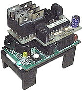 |
The High Power Cricket’s significant
improvement upon the plain Cricket is its high maximum voltage and output
power: Up to 30V DC may be used to supply the circuit, while the maximum
output current should not exceed 5A. The latter is not restricted by the
transistors, but by the 0.1 inch females headers used as output sockets,
as described in the previous section.
In contrast to the Pneumatic Cricket, where one MOSFET transistor was needed for each of the four outputs, the two output ports of the High Power Cricket are requiring four transistors each, which means that eight MOSFETs have to be placed on the printed circuit board. |
The circuit that has been implemented is very similar to the internal realization of the TC4427 motor driver that is used on the Cricket itself: For each motor output, it is a full H-bridge formed by two pairs of N-type and P-type MOSFETs. This kind of circuit is needed since there is no negative power source available – otherwise, one pair of transistors per output would be sufficient.
- Schematic
The photocoupler part, which can be regarded as the ‘left side’ of the board, is identical to the one on the Pneumatic Cricket.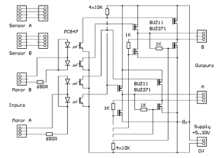
On the power side, each motor output is connected as a ‘bridge’ between two pairs of P-type and N-type MOSFETs – like the horizontal dash in an ‘H’. Initially, both side of the bridge are on the same electrical potential (both N-type FETs are closed, both P-type FETs are open), which means that there is no voltage across the motor.
If one of the pho-to-coup-ler’s output transistors becomes active, the N-type FET that is connected to it opens, closing the opposite P-type FET by cutting the current through the crossover 1 kOhm resistor at the same time. Thus, there is now a current path from the positive pole all the way through the N-type FET, the motor, and the P-type FET to the negative pole, driving the motor.
In case that the other photocoupler transistor is active, the same procedure works the other way round – the motor runs in the opposite direction.
Due to the special input circuit on the Cricket side, there is no possibility to activate both photocoupler transistors at the same time, which would be an ‘only once mode’ – all FETs would be closed, causing a short circuit across the power supply!
- Parts List and Layout
Just like the parts used for the Pneumatic Cricket, these are standard parts that should be available at most electronics stores. The order numbers refer to the Conrad mail-order catalog.| Amount | Type | Description | Order Number |
| 4 | BUZ 11 = IRFZ34N | N-type MOSFET | 15 94 41 |
| 1 | 22µF 50V | Capacitor 8x6.5mm | 47 29 05 |
| 1 | PC847 | 4 photocouplers | 18 70 20 |
| 2 | 680R, 1/4W, 5% | Resistor | 40 32 37 |
| 2 | 4x10K, 1/8W, 2% | Resistor Network, 5 pins | 41 60 29 |
| 4 | BUZ 271 | P-type MOSFET | 15 96 46 |
| 4 | 1K, 1/4W, 5% | Resistor | 40 32 53 |
| 2 | Male 8 pin header | Cut: 2+6+4+4 pins | 73 94 48 |
| 1 | Female 20 pin header | Cut: 4+4+3+3 pins | 73 63 50 |
| 1 | 2 pin, 3.5mm grid | Supply cable connector | 72 99 81 |
When MOSFETs turn on (close), they have an ON resistance called RDS(on). While it is quite easy to find N-channel types with very low RDS(on) ratings, P-channel MOSFETs have a higher resistance. The types that have been chosen to build the H-bridges have RDS(on) ratings of 0.03 Ohms and 0.13 Ohms, respectively. Although the P-types get warmer in the bridge circuit, they can still be used easily without heat sinks at the specified 5A maximum current.
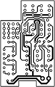
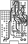
The High Power Cricket layout is so dense that a single-sided board is not possible. Thus, a two-layer board has been designed for these add-on modules. In the above illustration, the left part is the bottom layer, while the top layer is shown to the right, both viewed from the top.
To build up the board, five vias have to be inserted at the very small pads. When these holes are drilled with a 0.6mm drill, cut-off wires from standard resistors can be used for the vias in the very beginning.
The left side of the board (including the IC, the male and female headers, and the 680 Ohm resistors next to the IC) is built up exactly the same way as on the Pneumatic Cricket board. These parts, as well as the two-pin support for the piezo beeper, should be mounted before adding the components on the right side.
Note that of the two 10 kOhm resistor networks placed directly above the power supply connector, the lower one has the common pin on the left side, while it is on the right side at the upper resistor network. Four single 1 kOhm resistors are mounted below the MOSFETs in upright position. This is easy when every other resistor is turned by 180 degrees.
All MOSFETs should be inserted in the very end to protect the sensitive devices from static discharge. The lower row of transistors is filled with the P-type FETs, while the upper row takes the N-channel types. All transistors are placed with their heat sinks pointing to the right.