![[Jump to Cover]](cover.gif) |
![[Jump to Contents]](contents.gif) |
![[Jump to Introduction]](introduc.gif) |
![[Jump to Concepts]](concepts.gif) |
![[Jump to Realization]](realiza.gif) |
![[Jump to Conclusion]](conclusi.gif) |
![[Jump to Appendix]](appendix.gif) |
|
|
3.5 Additional Sensor and Actor Devices
According to the Cricket documentation, virtually any active or passive element which provides its reading in units of ohms can be used as an input device. To be more specific, its resistance value should be in the range of 1 kOhm to 50 kOhms, as the Cricket cannot discriminate resistances higher than 50 kOhms.The input reading from the sensor is polled by the Crickets PIC processor by applying a 5V DC test voltage to the input ports during the read cycle. The sensors response to this signal is detected and used to create the 8-bit sensor value.
Due to this flexible procedure, most variable resistors can be used directly as Cricket sensors. Variable resistors of different kinds are commonly used for the measurement of temperature, light, air pressure, etc. Therefore a great variety of sensors are available for the Crickets by just purchasing the desired parts from an electronics store.
 |
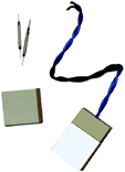
The figure to the left shows a sketch of
a standard 0.1 inch male header as it is used both for input and output
plugs. This particular part is a sensor plug, as it has three pins in an
asymmetrical layout. This encoding is very important in order not to confuse
the polarity of the sensor plug, because some sensor devices may be critical
to reverse voltage.
|
| Please note that
the next gereration Crickets, the so-called Red Dot Crickets, use 4-pin
sensor plugs that are incompatible with the ones describes above. See the
MIT Media Labs documentation for more information.
|
|
 |
Sometimes, there is the wish to connect
ordinary switches to the Cricket input ports. They may be of the type shown
on the picture to the left, but they may as well be mic-ro-switch-es, mercury
switches, or of any other kind. This is fairly simple to realize, as the
pair of wires that come from the switch just have to be soldered to a sensor
plugs signal + and signal pins.
|
| However, there is
one thing that should be paid attention to: Although the sensor plugs are
encoded by the unused pin as shown above, they still fit into the Crickets
output ports. If this happens, both the attached sensor and the Cricket
can be destroyed by excessive currents!
For this reason, it is suggested to insert a small 1kOhm resistor into one of the sensor lines, e.g. directly at the switch or at the sensor plug. This value will not harm the reading of the switch as it is still close enough to zero ohms. |
|
 |
A touch-less sensor is also great
for many purposes, as to kids, it sometimes appears like magic. But the
Lego-compatible sensor shown to the left is not magic, just magnetic
one of the tiny reed contacts in the upper corner of the picture has been
integrated into a flat type of Lego brick.
While the small glass tube just fits into the larger one of the two bricks at an angle of 45 degrees, the other Lego brick takes a tiny yet powerful bar magnet, diagonally as well. |
| When the two pieces
approach each other closer than eight millimeters, the reed switch is triggered
by the magnetic field and closes its contact. However, this happens only
if the glass tube and the magnet are at a perpendicular position. Thus,
the sensor can also be used as a revolution counter, as the contact will
open and close twice when the magnetic piece is rotated by 360 degrees.
Just as commercial Lego switches do, this touch-less sensor already contains a 1kW resistor in its housing, so no external protector is needed here. A second one will not hurt however, so when in doubt, you better add a resistor at every sensor plug. In the way that has been shown with the above examples, many useful sensors can be created for the Crickets. Most of the switches and variable resistors are also inexpensive parts which kids may use and modify in order to learn how natural parameters like temperature, pressure, and brightness are converted into their electrical equivalents, voltage or current. |
|
| Inspired by the Crickets new
ability to control four actors at the same time, some girls suggested to
build up a Cricket "light show" using a couple of differently colored light
bulbs. 12V, 4 watt bulbs have been chosen for this purpose, as up to 15
pieces of the same color could then be connected in parallel for great
disco effects.
|
|
The various motors and pneumatic applications have thus been added by visual effects. Equipped with the add-on modules, the Crickets are now open to any future ideas.
3.6 Mechanical Preparations
As announced in section 3.3, there are some mechanical adapters and extensions that have been created in order to make Festo pneumatics, Märklin Metall, and Lego Technic compatible to each other.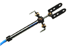 |
While Märklin Metall is very adequate to serve as a mechanical basis for pneumatics applications due to its high strength and durability, there is no standard piece in the construction kit that would fit to the cylinders. To provide a solid fixing of the Festo micro cylinders to a Märklin model, the adapter shown to the left has been created. |
On a 3-hole Märklin Metall piece, the middle hole has been enlarged to 8mm in diameter and supported on each side by a washer (1mm thick, 8mm/12mm inside/outside diameters). To the piston rod, a U-shaped part has been attached as shown on the picture.
This construction can be identified on the picture of oil pump model. In a similar way, Lego parts have been modified in order to serve as connecting links between pneumatic cylinders and Lego Technic. Since Lego parts are made of comparably soft plastics, those adapters are easier to build.
Pneumatic flow control valves are intended only for double-acting cylinders, where they are used to regulate the air flow escaping the cylinder. On single-acting cylinders, you cannot control the escaping air, and the use of flow control valves at a cylinders inlet is not recommended due to less precise results.
However, when there is no need for high precision, this can also be done. Since the flow control valves from Festo are designed to be screwed into the double-acting cylinders M5 threads, adapters have been created. These allow two flow control valves to be connected to each other in opposite direction. The resulting pair of valves can now be inserted into the tubing next to a single-acting cylinder and allows the expansion and contraction of the cylinder to be adjusted separately.
|
|