![[Jump to Cover]](cover.gif) |
![[Jump to Contents]](contents.gif) |
![[Jump to Introduction]](introduc.gif) |
![[Jump to Concepts]](concepts.gif) |
![[Jump to Realization]](realiza.gif) |
![[Jump to Conclusion]](conclusi.gif) |
![[Jump to Appendix]](appendix.gif) |
3.7 Programming and Testing
During the mentoring sessions at the CCE, several models have been designed and built up with the kids. Both mentors and the kids had the ideas for these applications, which have been used to test the Crickets’ improved abilities.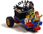 |
The Pneumatic Cricket and High
Power Cricket add-on modules are now integrated into the system so that
at the CCE, the term "Crickets" no longer refers to just the microcontrollers,
but implies the use of the add-ons, as well.
Before this project, the Crickets were only able to drive the Lego micro motors shown on the rear wheel of the small vehicle to the left. |
In this section, a few models will be described that have been constructed during the last months. For the Logo program code running on each model, please see the listings in Appendix B.
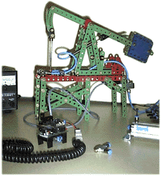 |
The oil pump shown to the left
was the first model to take advantage of the new Pneumatic Cricket add-on.
This was created at the time when the first Märklin Metall parts had
arrived at the CCE.
To learn about the possibilities of this metal construction system, a couple of kids decided to build up a working model as described in the Märklin manual and then modify it in order to be powered by pneumatics. |
| Originally, this
model of an oil pumping station was equipped with a wheel drive that moved
the beam up and down with a connecting rod. The wheel bearing is still
visible in the back. Later, the drive has been removed to be replaced by
a Festo micro cylinder. This has been attached to the model using the Festo-Märklin
adapter prepared before. By means of two flow control valves connected
to each other in opposite direction and inserted into the tubing next to
the cylinder, the beam’s speed could be adjusted separately for the up
and down movements.
The Cricket program for this model is extremely simple. It tells the pneumatic valve to open, wait for one second, close, and then wait for one more second before opening again. This is done in an endless loop. By means of the two flow control valves, the times that the cylinder needs to expand and contract has been adjusted to one second each, so that a continuous movement of the beam is achieved. For the oil pump model, two Cricket programs have been created using both plain Logo code and the GrafLogo interface. This has made kids and mentors familiar with the software and the procedure of transferring the program code from the PC to the Cricket, using the so-called Interface Cricket. |
|
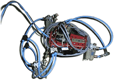 |
When they felt the enormous power
of a cylinder expanding at full speed, some of the kids created gun-like
machines, trying to hit intended targets with small Lego blocks.
Others had the idea to attach cylinders to a few left-over Märklin Metall pieces, pointing the pistons down towards the floor – the funny-looking Grasshopper was born. |
| This vehicle has
been changed and optimized during two days. In its final version, the Grasshopper
can be controlled with a Sony TV remote sending commands to the Cricket’s
IR interface: ‘jump forward’, ‘jump backward’, ‘jump vertically’, ‘bow
forward’, ‘bow backward’!
The pneumatic valves are controlled by the Cricket program in such a way that to jump forward, e.g., first the rear cylinders and a 10th of a second later, the front cylinder expand at full power. Air and electricity is supplied through six meters of tubing and wire. |
|
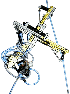 |
The most complicated model that
has been built so far is called "Free-Climber" (compare to the sketch in
section 3.1). This has been designed and realized by a group of mentors,
combining Lego Technic parts and pneumatics.
Based on the ideas to cling to a vertical rope with a pair of clamps that activate by turns, and to change the distance between the clamps using a third cylinder, the Free-Climber performs snake-like movements to climb up and down the rope. |
3.8 Creating the Web Documents
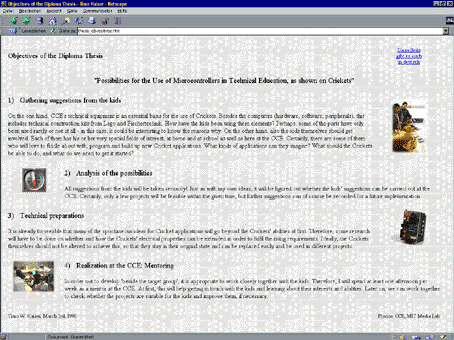
During the first weeks of the project, several pages have been designed for the World Wide Web. These were intended to introduce the diploma thesis to everyone who may be interested in the project: mentors and kids at the CCE, students and staff at the Esslingen Universities of Technology and Social Sciences, sponsoring companies, and others.On these documents, the objectives of the diploma thesis as well as the minimum technical requirements have been explained. As an example, the following is a screen shot of the page about the thesis’ objectives, taken from a high-resolution screen (1152 by 864 pixels):
In order to meet the requirement of designing pages that provide an attractive layout on different screens and in different browsers, emphasis has been laid on the arrangement of texts and images. When viewed using a low-resolution screen (640 by 480 pixels), the same page will look like this:
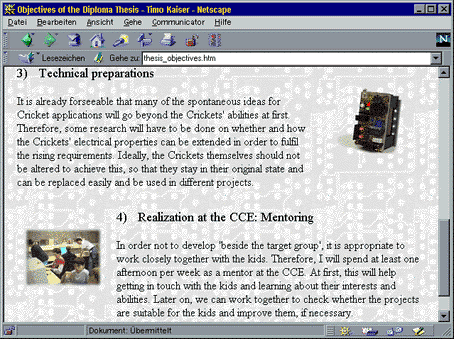
The page layout has been managed by intensive use of tables, with their borders set to zero pixels in order to make them invisible. All images have been included in GIF format, as this offers lossless compression to rather small file sizes.
Since the year 1997, all new browser software can subdivide their display window into several areas. Although the borders in between are not necessarily visible, these areas are called frames. It is popular to display a navigation bar in the left or bottom part of the screen. However, new generations of hand-held computers and TV add-ons (‘set-top boxes’) are being developed at this time, which will not support frames (and no JavaScript, either). This was the reason for not using frames on the Web pages.
In accordance with the project schedule, the HTML pages for online reading of the thesis will be created after the completion of this printed documentation (see the table in section 2.1). For the pages you are reading, a slightly different layout has been created:
The ring binder appearing to the left is in fact a background image. When the pages are viewed on the screen, this provides a constistant look and in spite of the unique appearance, the thesis online documentation recalls the usual print-style layout. On a printout of the pages, however, the binder image will not appear. Instead, there will be a blank column allowing the papers to be filed in a ‘real‘ ring binder.
In order to achieve a high image quality, all illustrations have been downsampled from the original 300-dpi true-color files to 72-dpi GIF files, so they could be inserted into the HTML pages without being resized by the browser. Where more detail was required, larger images have been linked to the small ones. By clicking on the small images, the reader may open the full-size versions in a separate browser window.
At the very top of each page, chapter labels allow to jump to the beginning of selected main sections, while the ‘Previous‘ and ‘Next‘ arrows at the top and the bottom of each page point to the beginning of the adjacent pages for continuous reading.
Like on the pages created in the beginning, the arrangement of text blocks and illustrations has been done with the help of many invisible tables in order to achieve an appealing layout on different screens (from 640 up to 1280 pixels wide). The ‘Objectives‘ section 2.2 (objectiv.htm) may serve as an example for this.